
Timberkits Oilfield Pump Jack

At fist I thought this model was goofy-looking with the Godzilla-sized oil worker. But then I did a little research and found that there are indeed pint-sized pump jacks in service. So perhaps the scale of the oil guy isn't so out of whack after all.

Finished model.

Finished model.

The cam and clasp bar assembly is connected to the oil guy via a balance arm under the base.
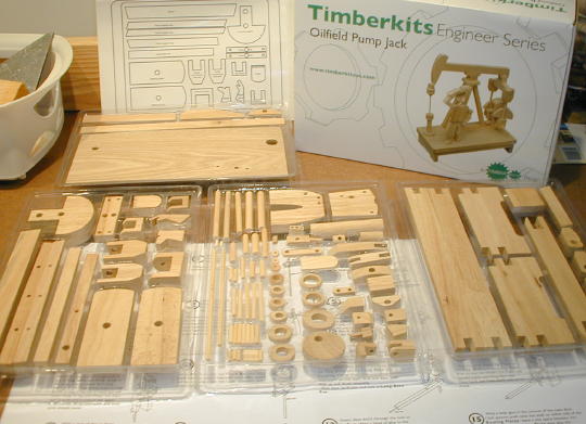
Box, parts and instructions.
The kit includes two torso plates for forming the front and back of the body. One of my plates had the big hole drilled in the wrong location. I temporarily pegged the two plates together and used the good plate as a template to drill a new hole through the defective plate. After drilling the new hole the two plates were interchangeable. Nevertheless, I used the defective plate as the back plate so the extra hole would be less noticeable.

Using the good plate as a template to drill a new hole in the defective plate.

Here are both plates after drilling. Red X indicates the incorrect hole.

This picture shows the oil guy's innards before gluing on the front plate.
I was concerned that I may have applied an insufficient amount of glue between the cam and cam shaft. To ensure that the cam doesn't slip on the shaft I drilled a small hole into the edge of the cam and through the shaft. I broke off a length of toothpick, dipped the toothpick in glue and stuffed it in the hole. Now I'm sure the cam is locked to the shaft.

Red arrow indicates my toothpick cam pin.
I ran into a snag as I prepared for final installation of the balance arm. The oil guy's range of motion was slightly less than the range of motion of the cam and clasp bar assembly. In other words, the oil guy would top out before the cam hit bottom dead center. Likewise the oil guy would bottom out before the cam hit top dead center. Had I glued everything together as is the cam was going bind at top dead center and/or bottom dead center. Fortunately I had not yet glued the balance arm's center pivot pin. I drilled out the pivot hole to about twice its original diameter. The idea was to create enough slop in the balance arm to compensate for what ever was wrong with my oil guy. It worked.
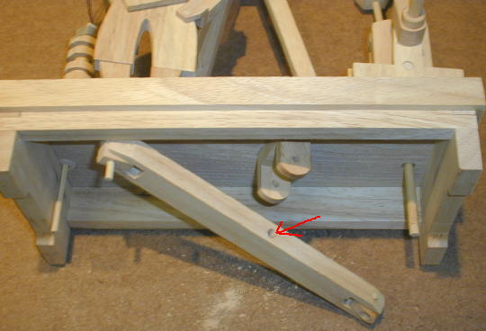
Red arrow indicates the enlarged balance arm center pivot hole.
I do not know what error I may have made to cause the above problem. I could not modify the oil guy because his glue had already been dry for several days. Nevertheless, I was able to determine that the oil guy's range of motion is limited by the "T End" at the top of the 3x115 rod. The T end hits the bottom of the right upper arm at one extreme and hits the leg unit at the other extreme. If I were to build this model again I would modify these contact points to give the oil guy a slightly greater range of motion.
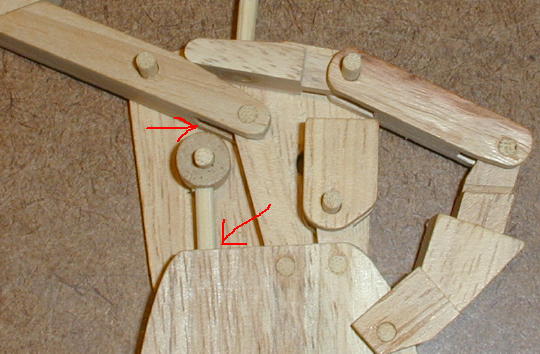
Red arrows indicate contact points between the right upper arm, T end and leg unit.