Timberkits Rocket

--EXTERNAL LINK-- Click image to go to YouTube video of finished model.

Finished model.
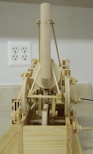
Finished model.
Finished model.

Finished model.
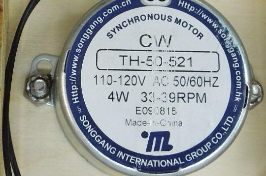
MK Motor Pack
The Rocket model is going to be a bit different from all my other Timberkits projects. I incorporated the Rocket into a motorized display using an MK Motor Pack kit (available from mechanicalkits.com).

Motor Pack package.

Assembled Motor Pack.
The motor is secured to the front face of the box with a pair of screws and nuts. The supplied nuts were a bit too big to clear the motor housing, so I ground down one side of each nut.
Motor housing mounted with modified nuts.
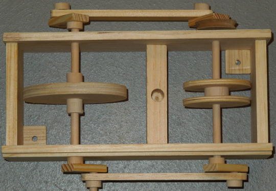
The motor kit comes with two big pulleys and one small. I drilled through one of the large pulleys and installed a setscrew. The screw threads into the pulley and passes through the hole in the motor shaft. Then I glued the small pulley onto the big one. This two-pulley arrangement allows for two drive speed options. Or the motor can be used to power two models at once.
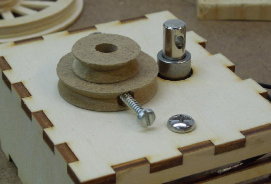
Double pulley and setscrew arrangement.

Double pulley on the motor shaft.
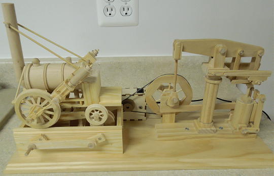
Motorized Display
The display base is made from a 7" x 20" pine board. I used a router to add a decorative edge around the board. The Motor Pack is mounted to the display base with a pair of screws. For future access, I did not glue the top and rear panels of the Motor Pack box. The panels fit tight and stay together on their own.
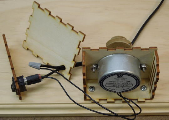
Motor Pack wired and mounted to the display base.
The Beam Engine was my first and still favorite Timberkits model. I incorporated the Beam Engine into my motorized display along with the Rocket. Using small triangular and round files, I carved a drive band grove around the circumference of the Beam Engine's big flywheel. This was a somewhat tedious process since the model was already fully assembled.
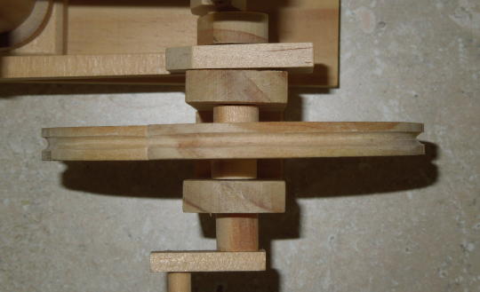
Flywheel with drive band grove.
To connect the Motor Pack to the models I used the spring-like drive bands that are popular with tinplate live steam toys. Do an Internet search on "Mamod drive bands", for example. Each spring has a tapered end that threads into the other end to form a band. Unlike a preformed rubber band, the spring bands can be added after the models are fully built. The spring bands can also be cut to length or combined for any size. A conventional preformed rubber drive band would not have worked because the Beam Engine was already built.

Spring drive bands.
Stephenson's Rocket
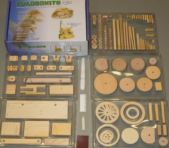
Box and parts.
I made some modifications to the Rocket's base in preparation for incorporating the model into the motorized display described above. First I replaced one of the axle spacers with one of the big pulleys from the Motor Pack. Then I added two small blocks to the inside opposing corners of the base. These blocks or mounting tabs are used to screw the base to the display.

Pulley.
Mounting tabs.

--EXTERNAL LINK-- Click image to go to YouTube video of finished base.
I like to build these models with a lot of "play" between moving parts. After the model is finished I go back and add shims if need be to tighten things up. In this case I added two layers of toothpick shims to each of the front axle blocks to better center the front axle.

Toothpick shims to center the front axle.
The Rocket is driven by friction. Therefore the parasitic frictions of the locomotive's axles and steam cylinder linkages must be less than the frictions between the drive disks. Every effort must be made to get the locomotive running as free as possible.
The instructions call for the pivot block to be glued to the support column such that the swing arm is horizontal. I thought the locomotive ran better with the swing arm slightly above horizontal. I also thought the model might run better if the pivot block were allowed to float on the support column. So I drilled a hole through the support column and glued in a piece of round toothpick. The pivot block rides on the toothpick.

Toothpick for supporting the pivot block.
Before placing the locomotive on the base I dropped a spare spacer down the support column hole. This raised the locomotive relative to the base drive disks such that the locomotive axles were better vertically centered in the axle blocks. Instead of gluing, I allowed the support column to float in the cross support hole. Gluing might be better. I'm still undecided. Sometimes it's better to let everything float where the parts are allowed to find their own "sweet spot" as the model is run.

Dropping a spacer down the cross support hole.
The kit comes with a cardboard crest to wrap around the top of the stack. I wasn't interested in having a piece of white cardboard on my otherwise wood model so I left it off.

Cardboard stack crest.
Despite my efforts to get the locomotive running as free as possible, it didn't work as well as I had hoped. The locomotive doesn't run smooth on motor power as can be seen in the video at the top of the page. Using the spring drive bands was probably a mistake. The springs tend to amplify any inconsistencies in the movement. I even tripled up on the bands, but they're still too springy. The glue is dry so it's too late to go back and try a rubber drive band.
Another mistake was trying to get the locomotive to run in super slow motion. I like slow motion. But I should have used a different pulley ratio to get the locomotive running faster. The locomotive runs much better at higher speeds when all the rotating parts are carrying momentum. In the end I had better results with the hand crank. The model actually runs pretty well on crank power.
The Beam Engine works better on motor power because it's a smoother running model and because the spring drive band has a better mechanical advantage over the Beam Engine's large flywheel pulley.

Triple spring drive belts.