
Plywood Twin Horizontal Engine
Started 2017. I'm seeing this engine as a long-term project. So who knows when the webpage might be finished? Answer: Never. The project languished for ten years then became kindling.
Having surfed around YouTube I found a bunch of people who had made one of these wood air engines using plywood and other wood scraps. As of 2015 I hadn't noticed anyone who incorporated a two-cylinder design with reversing valve gear. So I thought I'd give it a try. I'm more comfortable working with wood than metal. I also wanted to build something much more massive than the other live steam models in my collection. I like an engine that can run slow and I though a larger two-cylinder design would accomplish that function.
Construction
I made all this up as I went along. There are no plans. But I did take dozens of pictures along the way. If you have some rudimentary understanding of how steam engines work, you ought to be able to reproduce the engine from the information below. I pretty much just built what "looked right" to me. That's the extent of my engineering.
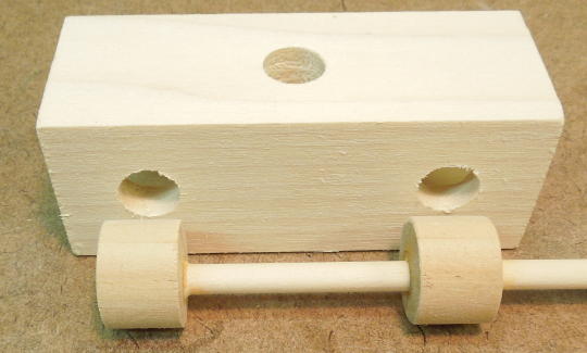
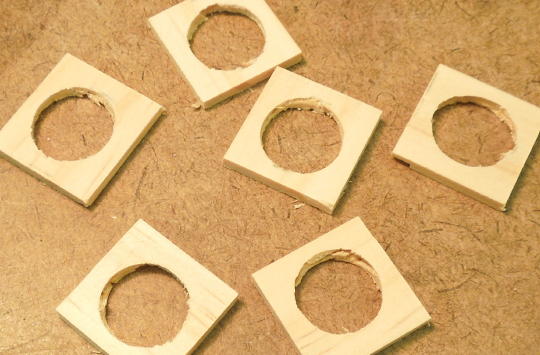
My pistons are 4" by 4" squares with a 6" travel. First I cut six identical 4" by 4" squares from ½" plywood. I divided the squares into two sets of three and added alignment marks to maintain their orientation as I bored holes for the piston rods. Each set of three is for a piston and two cylinder ends. Since the piston rod will extend through both cylinder ends, I won't bother with any sort of crosshead arrangement.
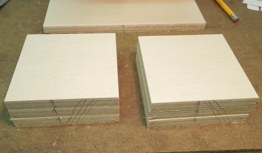
Pistons and cylinder ends.
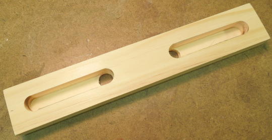
Using more ½" plywood I cut two 8½" by 9" pieces for the bottom and top cylinder walls. I cut a 4" by 9" piece for the center cylinder wall. And I cut two 5" by 9" pieces for the side cylinder walls. For what it's worth, I cut every piece such that the wood grain runs parallel with the motion of the piston. The side cylinder walls also have two ½" cylinder ports.
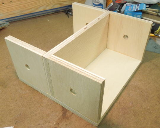
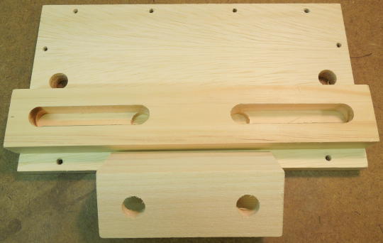
Cylinder ends and center cylinder wall glued to the bottom cylinder wall.
Top cylinder wall glued in place and side cylinder walls screwed in place.
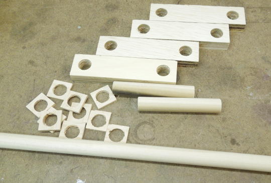
I wanted to make piston-type valves, but I had to work within the limitations of my drill press which was not ideal for boring holes through long blocks of wood. Best I could do was a valve block 4" long. So my valve block is made from 2 by 2 stock, 4" long, with a 7/8" valve bore through the center. I drilled one middle ½" hole for the intake port and two outer ½" holes for cylinder ports. There are no exhaust ports per se. Exhaust simply blows out either end of the valve bore. I was able to drill cleaner port holes by stuffing a scrap of 7/8" dowel through the valve bore before drilling the ports.

Valve block.
My piston valves are made from 7/8" and 1/4" dowel. I drilled 1/4" holes through the 7/8" dowel, cut 5/8" pucks and assembled the valve as shown. The valve stem is excessively long because I don't know how long it should be. I'll cut it down later.
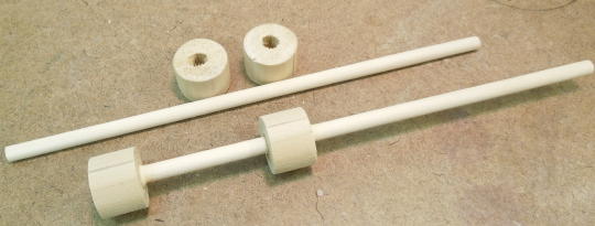
Piston components.
Piston compared to valve port locations.
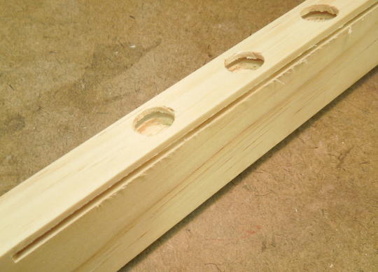
Next I needed a means for connecting the cylinder ports on the valve block with the cylinder ports on the side cylinder wall. I used 1 by 2 stock cut the same length as the cylinders. I drilled ½" holes corresponding to the valve block holes. Then I used a router to carve ½" channels which extend out toward the holes on the side cylinder wall. I could have eliminated this part entirely had I had the ability to fabricate a longer valve block. I glued together the side cylinder wall, the channel part and the valve block to form a complete valve assembly. I made a complete spare valve assembly for the right side which I'll later use to make a cutaway valve display.
Channel part.
The three valve parts showing how the cylinder ports line up.
Completed valve assemblies.
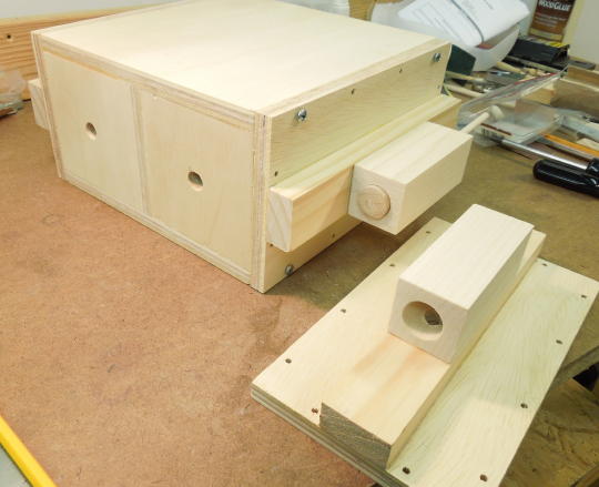
I made an intake manifold from ½" copper pipe fittings. First I made a flange from ½" plywood. A pipe fitting threads into a hole in the flange and the flange is screwed to the underside of the valve assembly to mate with the intake port. I drilled a 5/8" hole into the flange and was able to force-thread the fitting into the hole. After soldering all the fittings I buffed the manifold with a wire wheel and sprayed it with clear lacquer. Then I spread some glue on the pipe threads and re-threaded the flanges.
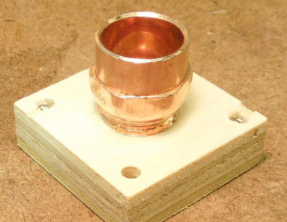
Flange.
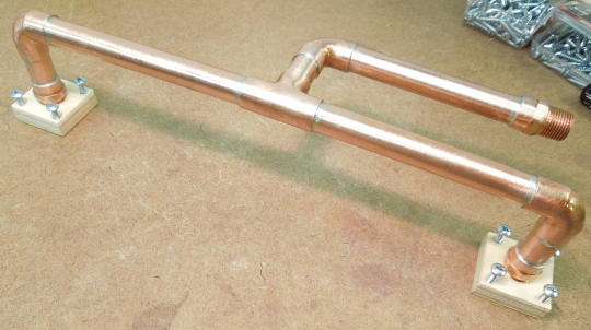
Finished manifold.
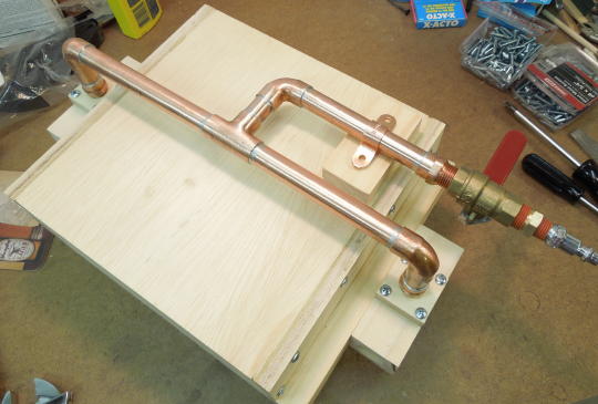
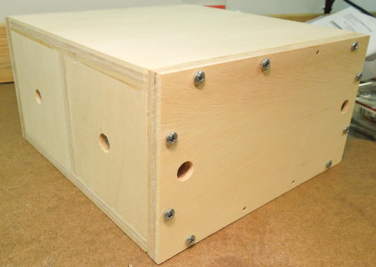
Manifold installed on the underside of the engine.
I needed a bunch thin spacers for the crankshaft. I drilled ½" holes into a piece of 1 by 2 stock. Then I ripped the stock down to a thickness of 1/8". Then I chopped the resulting strip into ¾" squares.
Making spacers.
Finished spacers.
I'm easily distracted by other hobbies. So now its 2017 and I'm picking up where I left off two years ago...
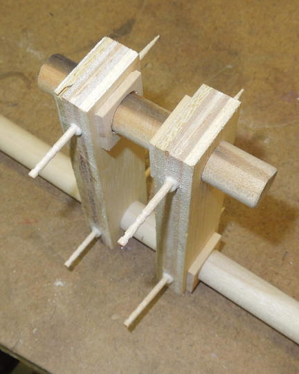
The crakshaft is made from ½" dowel and ½" plywood. The crank arm holes are 3" apart coresponding to a 6" stroke. The fit was too tight to effectively glue. So I drilled a small hole through each joint and glued in a toothpick to hold it all together. I didn't trust in my ability to make everything perfectly square. That's where the spacers come into play. The spacers are just glued in place and will keep the crank arms away from adjacent connecting rods and main bearings.
Crankshaft components.
Everything glued up.
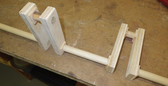
Finished crankshaft with all excess material cut away.
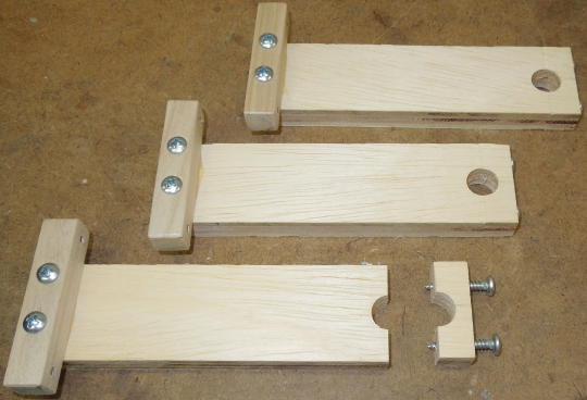
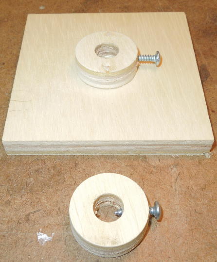
Next I made six crankshaft main bearings. First I cut rectangles of ½" plywood. Second, I drilled holes for the cap screws. Third, I cut away the caps. Fourth, I screwed the caps back on and drilled the crankshaft holes. Fifth, I glued and screwed a mounting flange to the bottom of each main bearing.
Crankshaft main bearings.
I glued a collar to each piston to accommodate a set screw. The set screw will be driven into the piston rod which will be made from ½" dowel.
A collar for each piston.